Tensile cable stayed bridges
Cable stayed bridges typically rely on compressive forces in
their roadways for their structural integrity.
Large compression structures are expensive and heavy, and
place a limit on the span of these types of bridges.
This page documents a more tensile design. The pattern is
based on that used by cable stayed bridges, but it manages
without a roadway that must sustain large
compressive forces.
Here is a model of such a bridge:
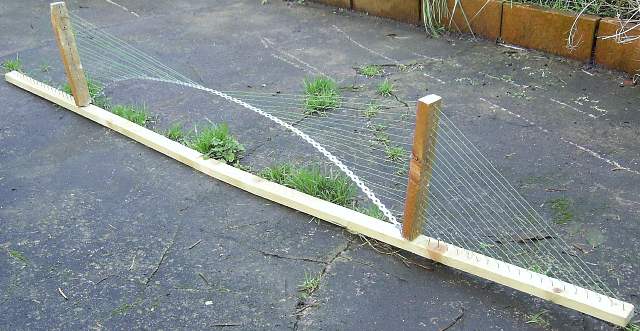
Bridge model
|
It resembles a cable-stayed bridge - but the roadway is
light and slender - and is incapable of supporting any
compression forces, as it would in the classical
cable-stayed pattern.
Suspension/cable-stayed hybrid
Use of large compression structures in a bridge results in
increased weight and expense - and clearly undesirable in
many cases.
I think a hybrid approach between suspension and cable-
stayed bridges is likely to be the best way to deal with
this issue.
First, to provide some visual context, here are the two types
of bridge in question:
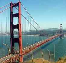
Suspension bridge
|
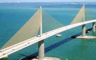
Cable-stayed bridge
|
The first observation is that if you pull on either end of
the cable-stayed bridge hard enough then you can take its
roadway out of compression - at the expense of reintroducing
ground anchors at either end.
Ground anchors - and their cost and associated environmental
disturbance - are often cited as one of the disadvantages of
suspension bridges.
However, if sustaining horizontal compression forces is what
is required, the earth is by far the cheapest, strongest and
best strut imaginable - and shifting the compressive forces
away from the ground and into a man-made strut running
parallel to it is unlikely to be a very intelligent move.
However pulling on the ends of the roadway is not a very
satisfactory solution. If the roadway is made of the same material
all along its length, then as the applied force takes the
compression out of the roadway nearest the piers, it is
simultaneously applying a huge stretching force at the point
furthest from the piers.
What it would be nice to be able to do is to apply tensile
forces of different magnitudes at different places along the
bridge's length - so the areas near the bridge piers have
the greatest forces applied to them. This can be done by
using a number of cables, running parallel to the roadway:
Cable-stayed bridge - normal
|
Cable-stayed bridge - hybrid
|
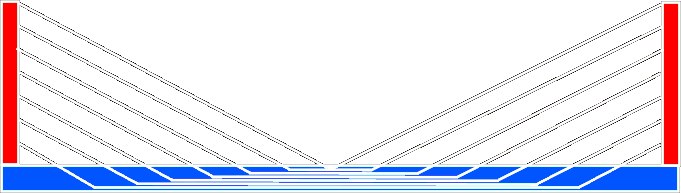
In the adjusted case, cables run along the bridge taking
the compression strain out of the bridge near the piers.
If all the cables run across - carrying the same
strain all along their length, then the opposite problem is
introduced - albeit much more mildly - the roadway becomes
under compression near its mid point.
There are two simple solutions:
- Anchor off one cable in six or so;
- Have different sections of the long cables carry
different strains - so the horizontal forces balance.
Either should be effective at preventing compressive forces
from accumulating along the span of the bridge.
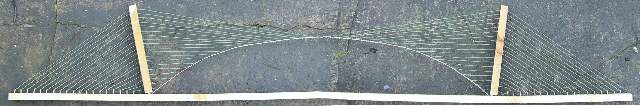
In the following model, the upward curve in the roadway has
been deliberately magnified, so its shape is visible.
The cables anchor very simply to the roadway - and do not
run across the full length of the bridge.
Ideally, the thickness and tensile strength of the
road should vary along its length, according to the tensile
force it needs to resist - but it is not critical if this
doesn't happen.
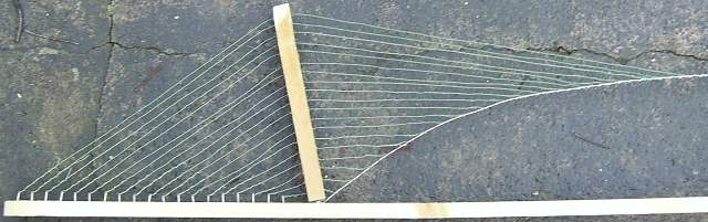
Bridge model - left hand side
|
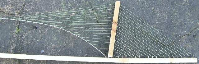
Bridge model - right hand side
|
Properties
The first thing to note is that the resulting bridge
looks like a cable-stayed bridge - though it may
not have so much heavy trusswork under the roadway.
The large ground anchors at either end of the bridge are
back - the resulting bridge is rather like a suspension
bridge in that respect.
The result scales upwards to large spans like a
suspension bridge does. The main problem that
prevents cable-stayed bridges from covering large spans is
eliminated by using this approach.
Relevance to suspension domes
If your bridge is not too long - and it has a heavy, static
roadway to support, which must sustain substantial point
loads, then you may already have a structure
capable of sustaining considerable compressive forces - so
withstanding additional compression forces applied by the
bridge's cables may not be such an issue.
However, in other cases the need to handle the large
compression forces from bridge's cables can easily become a
substantial point of difficulty.
The struts and trusswork required to sustain compression
forces are fundamentally heavy - and adding them is likely
to increase cost, weight - and the stresses and strains on
all other parts of the structure.
Usage
Is this idea of a hybrid cable-stayed/suspension bridge
actually in use?
Possibly. However, so far I have not encountered the design
in the literature - and the evidence I have gathered so far
about existing implementations is not very strong.
One of the main observable features of such a design is that
the roadway forms a catenary curve - similar to that
commonly found in many suspension bridge designs.
While most cable-stayed bridges seem to have pretty flat
roadways, some do bulge upwards in the middle - e.g.:
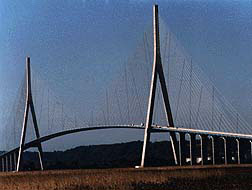
Seine River, Normandy
|
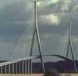
Seine River, Normandy
|
Unfortunately, there are other possible reasons for the road
of such a bridge bulging upwards in the middle besides it
being in tension.
Such an upward bulge in the roadway:
- could form a compression arch - which may be seen as being desirable;
- increases shipping clearance;
- reduces the lengths of the cable stays;
- increases the angles the cables make to the roadway;
- improves drainage: avoiding water pooling on the roadway;
- can improve aesthetics sometimes.
The idea of reducing the lengths of the cables (and
increasing the angles the cables make to the roadway) would
suggest that the resulting bridge roadways form two
straight sections, with something close to a fold in
the middle.
That does appear to be the pattern used in a number of
bridges - e.g.:

Queen Elizabeth II bridge diagram
|
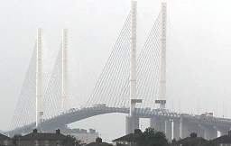
Queen Elizabeth II bridge
|
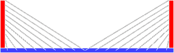
The profile of a hybrid cable-stayed/suspension bridge is
rather different - it tends to be flattest in the middle,
with the curvature concentrated near the ends:
Bridge model - roadway flattest in the middle
|
This suggests that such bridges are not really
using the principle described on this page - and instead
have a roadway that bulges upwards in the middle for
different reasons.
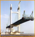
Another possible approach to detecting such bridges
involves examination of the construction method - via
photographs.
A classical cable-stayed bridge would be constructed
from the piers outwards. I have collected some photographs of
this process - see the links at the bottom of this page.
Construction of a hybrid cable-stayed/suspension bridge
would be most likely to involve throwing a lightweight
framework right across the full span, and then fleshing the
structure out.
So far, I have not found any evidence of this latter
technique being used.
Near the bridge piers
The hybrid cable-stayed/suspension described here behave
sub-optimally near the bridge piers.
It can't possibly make sense to allow tensile forces to run
all the way across the length of the bridge, just to remove
a few minor compression forces at either end of the bridge -
yet that is what happens when cables are applied near the
piers.
It seems reasonable to allow portions of the roadway near
the bridge piers to bear some compression loads - by using a
simple trussed structure there - in order to prevent the
resulting horizontal forces being carried right across the
bridge.
Hybrid bridge FAQ
There are some frequently asked
questions about this type of structure on another
page.
History
A history of my development of this idea may be
found here.
Links
Sutong bridge - under construction
Ravenel Bridge - under construction
SkyBridge - under construction
Alex Fraser Bridge - under construction
Bangcock Mega Bridge - under construction
The Second Severn Crossing - under construction
- also here
Roadway bridge across the River Vistula in Plock (Poland) - under construction
Shanghai East Sea Bridge - under construction
Pont De Brotonne - under construction
Cable-stayed bridge over Rio Guamŕ in Brazil - under construction
Bridge over the Rio Paranŕ a Las Palmas - under construction
Clark Bridge - under construction
Bai Chay Bridge - under construction - also
here and
here
| 
